Product Overview #
Introduction: The ThinkPad 730T is a compact pen-operated tablet PC aimed at enterprise and field workers.
Machine Type 2524 · 1993-94 · 18 sections
ThinkPad 730T and 730TE pen tablets.
Introduction: The ThinkPad 730T is a compact pen-operated tablet PC aimed at enterprise and field workers.
Note: The diagnostic tests are intended to test only IBM products. Non-IBM products, prototype cards or modified options can give false errors and invalid responses.
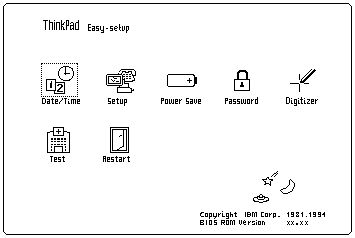
Note: If the Pen is not held on the Suspend button
when power is switched on, the user defined screen appears.
DID EITHER THE Easy-Setup or Password Menu SCREEN APPEAR ?
Note: The installed devices are displayed in dark shade and the uninstalled devices are displayed in gray shade FDD, Parallel and Serial icons are always displayed in dark shade. That is, these icons represent adapters on the system board and do not represent external devices.
DID THE TEST FIND A DEVICE ERROR?
A device error is displayed with an X over the device. The device ID (XXX), an error description code (YY), and FRU code (ZZZZ) are displayed: For example:
Note: If the test stops or hangs when the test is running, replace the last device that was tested.
General Checkout 730TE (2524)
Use the following procedure as a guide for computer problems.
NOTE: The diagnostic tests are intended to test only IBM products. Non-IBM products, prototype cards or modified options can give false errors and invalid responses.
 If more than one error code appears,
diagnose the first error code first. The cause of this first error code can cause
additional false error codes to appear. Multiple error codes may appear on the
LCD during POST process.
If more than one error code appears,
diagnose the first error code first. The cause of this first error code can cause
additional false error codes to appear. Multiple error codes may appear on the
LCD during POST process.
NOTE: If the Pen is not held on the Suspend button when power is switched on, the user defined screen appears. DID EITHER THE Easy-Setup or Password Menu SCREEN APPEAR ?
DID THE FOLLOWING SCREEN APPEAR ?
DID THE TEST MENU APPEAR ?
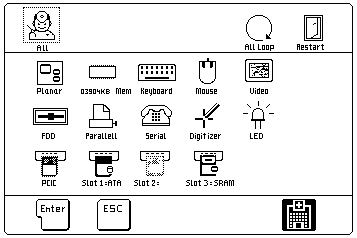
NOTE: The installed devices are displayed in dark shade and the uninstalled devices are displayed in gray shade FDD, Parallel and Serial icons are always displayed in dark shade. That is, these icons represent adapters on the system board and do not represent external devices.
DID THE TEST FIND A DEVICE ERROR?
A device error is displayed with an X over the device. The device ID (XXX), an error description code (YY), and FRU code (ZZZZ) are displayed: For example:

XXX: Device ID
YY: Error Description Code
ZZZZ: FRU Code
NOTE: If the test stops or hangs when the test is running, replace the last device that was tested.
Note: For IBM devices not supported by ThinkPad 730TE diagnostic code, refer to the manual for that device.
Symptom-to-FRU Index 730TE (2524)
The Symptom-to-FRU Index lists the symptoms and errors and the possible causes. The most likely cause is listed first. Use this index to help you decide which FRUs to have available when servicing a computer.
For errors indicated by the diagnostic tests, see 'FRU Codes'. If the symptom is not listed, go to 'Undetermined Problems'
In the following error codes, X can be any number.
NOTE: For IBM devices not supported by ThinkPad 730TE diagnostic code, refer to the manual for that device.
| Symptom/Error | FRU/Action |
|---|---|
| 10X | 1. System board |
| 100 (Check 'Memory Checkout' before changing any device.) |
1. IC DRAM Card
2. Memory Card 3. System Board |
| 111 |
1. Option Bus
2. System Board |
| 161 | 1. System Board (Backup Battery) |
| 162 (Check 'Installed Devices Check' before changing any device.) |
1. Check Device Configuration
2. System Board 3. Diskette Drive Assembly 4. Diskette Drive Cable 5. Hard Disk Card 6. Modem Card |
| 163 |
1. Set Time and Date
2. System Board |
| 164 (Check 'Memory Checkout' before changing any device.) |
1. Check Device Configuration
2. IC DRAM Card 3. Memory Card 4. System Board |
| 1XX | 1. System Board |
| 20X |
1. IC DRAM Card
2. Memory Card 3. System Board |
| 21X |
1. IC DRAM Card
2. Memory Card 3. System Board |
| 2XX (Check 'Memory Checkout' before changing any device.) |
1. IC DRAM Card
2. Memory Card 3. System Board |
| 301, 31X |
1. System Board
2. Keyboard 3. Port Replicator |
| 304, 305 |
1. System Board
2. Mouse 3. Keyboard 4. Port Replicator |
| 308 | 1. System Board |
| 3XX |
1. Keyboard
2. Mouse 3. System Board 4. Port Replicator |
| 601, 6XX (Go to the 'External Diskette Drive Checkout' before changing any device.) |
1. System Board
2. Diskette Drive Assembly 3. Diskette Drive Cable 4. Port Replicator |
| 602 | 1. Diskette Drive Assembly |
| 9XX |
1. System Board
2. Parallel Device 3. Port Replicator |
| 11XX |
1. System Board
2. Serial Device 3. Port Replicator |
| 12XX |
1. System Board
2. Serial Device 3. Communication Cable 4. Port Replicator |
| 17XX |
1. Disk Drive Assembly
2. System Board |
| 24XX |
1. System Board
2. LCD Assembly |
| 5001 - 5016 |
1. System Board
2. LCD Assembly |
| 5017 - 5020 |
1. System Board
2. LCD Assembly |
| 8601, 8603 |
1. System Board
2. Mouse 3. Port Replicator |
| 86XX |
1. Mouse
2. System Board 3. Port Replicator |
| 101XX |
1. Modem Card
2. System Board |
| 102XX | 1. System Board |
| I9990305 |
1. Operating System
2. OS Device |
FRU Codes 730TE (2524)
If an error is detected by the diagnostic tests, a four-digit FRU code is displayed.
The FRU code indicates two suspected FRUs.
Replace the FRU that is indicated by the two leftmost digits first, then replace the FRU indicated by the two rightmost digits. No FRU is assigned to code 00 If only one FRU is suspected, the other FRU code is filled with 00.
Use the 'External Diskette Drive Test' to isolate diskette problems to a FRU.
If the problem still remains and the system board has not been replaced, replace the system board.
| FRU Code | FRU |
|---|---|
| 10 | System Board |
| 11 | CPU Card |
| 20 | Memory (See 'Memory') |
| 30 | Keyboard |
| 31 | Numeric Keypad |
| 32 | Keyboard, External |
| 33 | Mouse |
| 36 | LCD / Digitizer |
| 40 | LCD Assembly |
| 41 | External CRT |
| 50 | External Diskette Drive |
| 60 | System Board |
| 65 | IC Card Memory |
| 68 | TPF Card |
| 68 | Hard Disk Card |
| 70 | System Board (Printer) |
| 71 | System Board (Printer control) |
| 85 | System Board (Speaker) |
| Symptom/Error | FRU/Action |
|---|---|
| Continuous beep | 1. System Board |
| One beep and blank, unreadable, or flashing LCD |
1. LCD Assembly
2. System Board 3. Memory Card 4. IC DRAM Card |
| One beep and the message 'Boot source cannot be found' |
1. TPF
2. System Board |
| One beep and the message 'Unable to access boot source' |
1. TPF
2. System Board |
| One long, two short beeps and a blank or unreadable LCD |
1. System Board
2. LCD Assembly |
| Five very short beeps | 1. Connect an AC adapter or install a fully charged battery. |
| Ten very short beeps | 1. Connect an AC adapter or install a fully charged battery (allow system to complete shutdown before changing the battery). System is shutting down due to low battery voltage. |
| Two short beeps | 1. POST error. Refer to 'Numeric Error Codes' list |
| Symptom/Error | FRU/Action |
|---|---|
| No beep, Power-on LED not lit, and a blank LCD during POST (See 'Power Systems Checkout' before replacing any FRUs.) |
1. System Board
2. Power source when failing |
| No beep, Power-on LED lit, and a blank LCD during POST (See: 'Power Systems Checkout' before replacing any FRUs.) |
1. System Board
2. CPU Card 3. Memory Card 4. IC DRAM Card 5. Modem Card |
| No beep during POST, but system runs OK | 1. System Board (Speaker) |
| LCD screen unreadable or characters missing pels. |
1. LCD Assembly
2. System board |
| One or more keys do not work |
1. Keyboard
2. System board |
| Printer problems. (See 'Printer Checkout' |
1. System Board
2. Port Replicator 3. Parallel Port Adapter Cable |
Use the following procedure if you suspect a computer power problem, for example:
Obtain from the user all information about the symptoms of the power failure.
REMOVE THE BATTERY. DOES THE COMPUTER FAIL ONLY WHEN USING THE AC ADAPTER ?
INSTALL A CHARGED BATTERY. DISCONNECT THE AC ADAPTER. DOES THE COMPUTER FAIL ONLY WHEN USING THE BATTERY ?
DID THE TEST RUN SUCCESSFULLY ?
Use the following procedure to analyze an AC adapter problem.
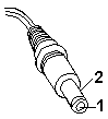
| Pin | Voltage (Vdc) |
|---|---|
| 1 | +14 to +16 |
| 2 | Ground (sleeve) |
Use the following procedure if you suspect a car battery adapter problem.
| Pin | Voltage (Vdc) |
|---|---|
| 1 | +14 to +16 |
| 2 | Ground (sleeve) |
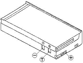
| Contacts | Voltage (Vdc) |
|---|---|
| + | +6.0 to +8.4 |
| - | Ground |
Use the following procedure to check if the thermal protection has tripped.
Use the following procedure to isolate the diskette problem to a controller, drive or diskette. A scratch, write enabled 2HD diskette is required.
Power off the system.
Remove or disconnect one of the following devices:
Any external device or cables (including the keyboard)
If a device is installed but the icon appears in gray shade rather than dark shade on the Test Menu, it means that the device is defective. Make sure that the device is connected properly. If the symptom continues, replace the device or the system board.
Use the following procedure to analyze a short or an open circuit in the computer.
| Symptom/Error | FRU/Action |
|---|---|
| Computer does not respond to Pen input. |
1. Pen
2. LCD Assembly 3. System Board |
| LCD backlight not functioning |
1. Inverter Card
2. LCD Assembly 3. System Board |
| LCD backlight intensity not adjustable |
1. Inverter Card
2. LCD Assembly 3. System Board |
| LCD contrast not adjustable |
1. LCD Assembly
2. System Board |
| System hang or intermittent hang (See 'Undetermined Problems' before replacing any FRUs |
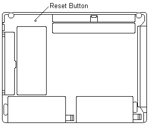
1. Press 'Reset Button'
2. System Board 3. Operating System |
| The system does not suspend or resume |
1. System Board
2. LCD Assembly |
| The system does not power off |
1. Press 'Reset Button'
2. System Board |
| Real-time clock inaccurate | 1. System Board |
| Printer problems (See 'Printer Checkout') |
1. System Board
2. Parallel Port Device Cable |
| Serial or parallel port device problems |
1. Device
2. Device Cable 3. System Board |
| LED incorrectly remains off, but system runs OK | 1. System Board |
| Modem Card does not communicate with a modem or FAX. |
1. Verify that the setup
data defined by the
communication software
is suitable for the communication
2. Modem Card |
If the problem remains, see 'Undetermined Problems'
Note: Before removing a IC DRAM card, switch off computer power.
NOTE: Before removing a IC DRAM card, switch off computer power.
To isolate the FRUs, remove the IC DRAM card and run the memory test again. Otherwise, replace the IC DRAM card. If an error occurs without the IC DRAM card, replace the memory card first. (The memory card contains the first 4 MB or 8 MB of the memory.) If the problem remains, replace the system board.
The reset button is used to power off the system when the system will not power off normally or when the system is hung.