ThinkPad Laptops

ThinkPad 701 'Butterfly'

Machine Type 2630 · 1995 · 75 sections

Iconic ThinkPad 701C/701CS with the TrackWrite expanding keyboard.

Overview #

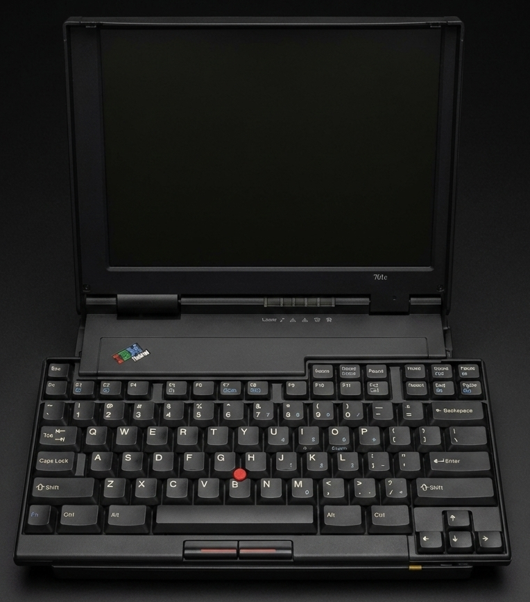
Introduction: The iconic ThinkPad 701 'Butterfly' is famous for its expanding TrackWrite keyboard, making it a masterpiece of industrial design.

Product Overview 701C, 701CS #

Product Overview 701C, 701CS (2630)

Feature Description
Processor Intel® 486 DX2 25/50MHz or DX4 25/75MHz, with math coprocessor
Memory (Standard) 4MB or 8MB (on the system board)
Memory (Option) 4, 8 or 16MB SO-DIMM
Bus Architecture (Two Busses)
  • Local bus for hard drive and video (with hardware line draw, BITBLT cursor, and sprite support).
  • ISA bus
CMOS RAM 128 Bytes
VGA Video
  • ThinkPad 701CS — 10.4 inch 640×480, 256/226K color DS-STN LCD color.
  • ThinkPad 701C — 10.4 inch 640×480, 256/226K color TFT LCD color.
Diskette Drive 1.44MB (3-mode for Japan, 2-mode for other countries) 3.5-inch external.
Hard Disk Drive (Removable)
  • 360MB, 2.5-inch
  • 540MB, 2.5-inch
  • 720MB, 2.5-inch (optional)
Audio
  • Built-in speaker
  • Built-in microphone
  • Microphone jack
  • Speaker/headphone jack
  • Line-in jack
  • Supports SoundBlaster and SoundBlaster Pro applications
Internal Modem Card Data/Fax/Voice Modem with 14.4 Kbps transmission rate and telephony support (U.S. and Canada only)
PCMCIA Cards Accepts any of the following:
  • One or two Type I
  • One or two Type II
  • One Type I and one Type II
  • One Type III
Infrared Transceiver Integrated infrared hardware IRDA-compatible transceiver with 115.2 Kbps transmission rate.

Checkout Guide 701C, 701CS #

Note: Before replacing any FRU, see 'FRU Removals and Replacements'

Checkout Guide 701C, 701CS (2630)

Service for U. S. and Canada

In the U. S. and Canada, the 701C / 701CS is serviced only through EasyServe.

Use the following procedure as a guide for computer problems:

  1. Ask the customer for as much detail as possible  about the failing symptoms.
  2. Verify the symptoms by attempting to recreate the failure  either by running the diagnostics test or by repeating the same operation.  (To run the diagnostics, refer to 'Running the Diagnostics' )
  3. Use the following table with the verified symptom to determine  which page to go to. Search the symptoms column  and find the description that best matches your symptom,  then, go to the page shown in the 'Go to' column.

NOTE: Before replacing any FRU, see 'FRU Removals and Replacements'

Symptom Go to
Power failure. (The power indicator does not go on or stay on.) 'Power Systems Checkout'
POST does not complete. No beeps or error codes are indicated. 'No-Beep Symptoms'
POST beeps, but no error codes are displayed. 'Beep Symptoms'
POST detected an error and displayed numeric error codes. 'Numeric Error Codes'
The diagnostics test detected an error and displayed a FRU code. 'FRU Codes'
The configuration is not the same as for the installed devices. 'Checking Installed Devices'
Other symptoms (such as LCD display problems). 'Symptom-to-FRU Index', and then use the symptoms tables.
Symptoms cannot be recreated. (Intermittent problems.) Use the customer-reported symptoms and also see 'Intermittent Problems'

General Checkout #

The diagnostic tests are intended to test only IBM products. Non-IBM products, prototype cards, or modified options can give false errors and invalid system responses.

warn

  • Only trained personnel should service the computer.
  • Drives in the computer that you are servicing  might have been rearranged or the drive startup  sequence might have been altered.  Be extremely careful during write operations  such as copying, saving, or formatting.  Data or programs can be destroyed if you select an incorrect drive.

Perform the following procedures to complete a general checkout:

  1. Power-off the computer and all external devices.
  2. Check all cables and power cords for correct connection.
  3. Power-on all external devices.
  4. Power-on the computer.
  5. Press the F1 key any time  while the POST memory count is proceeding.  The computer  emits one short beep at the end of POST and the  Easy-Setup screen screen appears.  If this does not occur,  go to 'Symptom-to-FRU Index'
  6. Run the advanced diagnostics tests.  For information on how to run the diagnostics  tests, see 'Running the Diagnostics' For information on how to disable the password,  see 'Removing the Power-On Password'
  7. Find your symptom in the table in 'Checkout Guide', and  then go to the appropriate page.  Otherwise, see 'Symptom-to-FRU Index' , and then  go to 'Undetermined Problems'

Running the Diagnostics #

Note: A graphic message prompts you to attach the selected test tools.

Use either the TrackPoint III or the cursor movement keys to interact with the tests. When asked for an OK response, press Enter or select the OK button.

  1. With the computer powered-off, attach any test tools  to the device to be tested.  For example, attach a wrap plug to the serial port on the MultiPort II  or insert  the PC test cards in the PCMCIA slot.- Power-on the computer.  Press the F1 key any time  while the POST memory count is proceeding.  When the memory test is completed, the Easy-Setup screen screen appears.- Select Test and press Enter.- Press Ctrl+A to enter  advanced diagnostics.- Select Tool to install a  test tool.
    • Select the test tool for a device,
      and press the spacebar or click button to install
      it.
      A OK mark appears for the selected device.
      Repeat this step to install multiple devices.
      NOTE: A graphic message prompts you to attach the selected test tools.
    • Select OK and press Enter
      if the selection is correct
    • Select a device and press Enter to start the tests
    • Select Test All to test all devices
    • Select Looptest to loop tests.
      A loop option menu appears in which
      you can select a loop test for one or more devices.
      Select a device and press the spacebar or click key.
      A OK mark appears for the selected device.
      Repeat this step to select multiple devices.
      Press Enter to start the diagnostics loop.
      If no device is selected,
      all device tests are looped.
    • To exit the loop,
      keep pressing Ctrl+Pause until the test exits.
      The system emits a beep sound to notify you that the
      test program has received the exit interrupt
    • Press Esc to exit the test screen
    • Choose Restart to leave Easy-Setup screen and restart your
      system
    • Select OK or press Enter
      to confirm the restart.

Symptom-to-FRU Index 701C, 701CS #

Note:

  1. Before replacing the top and bottom system boards,  try reseating the boards.  If reseating the boards does not  correct the problem,  replace the boards.- If possible,  install the latest level of BIOS available  before replacing any FRU.

Note: For IBM devices not supported by diagnostics codes of ThinkPad 701C / 701CS, see the manual for those devices.

Symptom-to-FRU Index 701C, 701CS (2630)

errorpi   Numeric Error Codes

The Symptom-to-FRU Index contains tables that list causes of symptoms. The most likely cause is listed first. Use this index to help you decide which FRUs to have available when servicing a computer.

warn1   pleaseREAD - see

Before removing any FRU, power-off the computer, unplug all power cords from electrical outlets, remove the battery pack, then disconnect any interconnecting cables.

Perform the FRU replacement or actions in the sequence shown in the FRU / Action columns. If the replacement FRU did not solve the problem, put the original FRU back in the computer.

NOTE:

  1. Before replacing the top and bottom system boards,  try reseating the boards.  If reseating the boards does not  correct the problem,  replace the boards.
  2. If possible,  install the latest level of BIOS available  before replacing any FRU.

Before completely reassembling a computer that has been repaired, try to reboot the computer to check the repairs that have been completed. However, when you reboot without the keyboard attached, the computer will display error codes 8603, 8613, and 86XX.

Use displayed numeric error codes to determine the system problem. If numeric error codes are not available, use the other symptom tables that describe specific symptoms. If the symptom is not listed, go to 'Undetermined Problems'

NOTE: For IBM devices not supported by diagnostics codes of ThinkPad 701C / 701CS, see the manual for those devices.

Numeric Error Codes 701C, 701CS #

Numeric Error Codes 701C, 701CS (2630)

Numeric error codes show the errors detected in POST or system operation. Use the error codes displayed on the screen to diagnose failures. If more than one error code is displayed, begin the diagnosis with the first error code. The cause of the first error code can result in false error codes being displayed.

In the following error codes, X can be any number.

Symptom/Error FRU/Action
02X, 101, 107 1. Battery
2. AC Adapter
3. Memory Option
4. Top System Board
10X 1. Bottom System Board
119 1. Top System Board.
161, 163 1. Set Configuration (Press Fn+F1 to enter the Configuration Utility and set the time and date.)
2. Top System Board.
3. Bottom System Board.
162 (Check the Installed Devices list for a missing device.) 1. Set Configuration. (Press Fn+F1 to enter the Configuration Utility and set your configuration.)
2. Any Missing Device.
3. Top System Board.
4. Bottom System Board.
164 (Memory size error) 1. If a SO-DIMM card has been removed, press Fn+F1 to enter the Configuration Utility, and verify the memory size.
2. Replace the installed SO-DIMM.
3. Bottom System Board.
184 1. Press Fn+F1 to enter the Configuration Utility, and then reset the Power-on Password
195 (The hibernate partition does not match memory size.) 1. Check if the disk drive is from another computer or if the memory size has changed.
2. Go to 'Hard Disk Drive Checkout'
3. Hard Disk Drive
196 (Read error occurred in the hibernate area of the Hard Disk Drive.) 1. Disable, and then enable Hibernate mode.
2. Go to 'Hard Disk Drive Checkout'
3. Hard Disk Drive
197 (The computer memory size is not equal to the hibernate area size on the Hard Disk Drive.) 1. Disable, and then enable Hibernate mode.
1XX (Not listed above.) 1. Top System Board.
2. Bottom System Board.
2XX 1. Go to 'Memory Checkout'
2. SO-DIMM
3. Bottom System Board
3XX (Before replacing FRUs, power-off, and then power-on the computer.) 1. Remove attached external devices.
2. Reseat cables.
3. Keyboard
4. Top System Board
6XX 1. Go to 'Diskette Drive Checkout'
2. Diskette
3. Diskette Drive Cable
4. Diskette Drive
5. Top System Board
09XX, 10XX 1. Top System Board.
11XX 1. Modem
2. Top System Board
3. Bottom System Board
17XX 1. Go to 'Hard Disk Drive Checkout'
2. Hard Disk Drive
3. Bottom System Board
24XX (For external displays, see the 'External Display Self-Test' in the 'Common Devices Checkout section' before replacing any FRUs.) 1. External Display.
2. External Display Power Cord.
3. Backlight Lamp Assembly.
4. LCD Assembly.
5. Bottom System Board.
6. Inverter Card.
8000 1. Set Configuration.
2. PCMCIA Card.
3. Bottom System Board.
860X (Pointing device error when TrackPoint III is disabled.) 1. External Mouse.
2. External Keyboard.
3. Top System Board
4. Bottom System Board
861X (Pointing device error when (TrackPoint III is enabled.) 1. Reseat the TrackPoint III cable (the narrowest keyboard cable) at the Top System Board.
2. External Mouse
3. Keyboard
4. Top System Board
5. Bottom System Board
86XX (Not listed above) 1. Pointing Device.
2. TrackPoint III.
3. Keyboard.
4. Numeric Keypad.
5. Top System Board.
6. Bottom System Board.
12902 1. Bottom System Board.
I9990305 1. Go to 'Hard Disk Drive Checkout'
2. Hard Disk Drive
3. Bottom System Board
Other codes not 1. Go to 'Undetermined Problems'
listed above

FRU Codes #

Note: The device ID and error codes are used to indicate in detail the portion of the FRU that caused the error. If replacing a FRU does not correct a problem, see the device ID or error code from the previous failure. If they have changed, the new FRU might be defective or incorrectly installed.

If an error is detected by the diagnostics tests, a four-digit FRU code is displayed, along with an error code. The FRU code indicates two suspected FRUs. Replace the FRU that is indicated by the two leftmost digits first, and then replace the FRU indicated by the two rightmost digits. No FRU is assigned to code 00. If only one FRU is suspected, the other FRU code is filled with zeros. See the referenced page before replacing the FRU.

FRU Code FRU/Action
10 1. Diskette Drive
2. Bottom System Board
3. Top System Board
12 Top System Board
14 Bottom System Board
20 Memory
(See 'Memory Checkout')
32 External Keyboard
33 External Mouse
40 LCD Assembly
(See 'Disassembling the LCD Assembly')
45 External CRT
50 1. Reseat the Diskette Drive (FDD-1).
2. Diskette Drive (FDD-1)
51 1. Reseat the Diskette Drive (FDD-2).
2. Diskette Drive (FDD-2)
55 1. Insert a correctly
formatted 2.0MB diskette
into the Diskette Drive.
60 1. Reseat the Hard Disk Drive (HDD-1).
2. Hard Disk Drive (HDD-1)
61 1. Reseat the Hard Disk Drive (HDD-2)
on the docking station.
2. Hard Disk Drive (HDD-2)
70 External PCMCIA
81 Internal Modem Card
91 If MultiPort II is installed:
1. Reseat MultiPort II.
2. MultiPort II.
If Dock II is installed:
1. Reseat Dock II.
2. Dock II

NOTE: The device ID and error codes are used to indicate in detail the portion of the FRU that caused the error. If replacing a FRU does not correct a problem, see the device ID or error code from the previous failure. If they have changed, the new FRU might be defective or incorrectly installed.

If the problem remains after replacement of the FRUs, go to 'Undetermined Problems'

No-Beep Symptoms #

Symptom/Error FRU/Action
No beep, power-on indicator not on, and a blank LCD during POST. 1. Go to 'Power Systems Checkout'
2. Top System Board.
3. Power sources.
No beep, power-on indicator on, and a blank LCD during POST. 1. Top System Board.
2. Bottom System Board.
No beep, power-on indicator on, and a blinking cursor only during POST. 1. Top System Board.
2. Bottom System Board.
No beep during POST but system runs correctly. 1. Turn the volume up.
2. Speaker.
3. Top System Board.

Beep Symptoms #

Symptom/Error FRU/Action
Continuous beeps. 1. Top System Board
One beep and a blank, unreadable, or flashing LCD. 1. Reseat all LCD connectors.
2. LCD Assembly
3. Bottom System Board
One beep, and the message Unable to access boot source. 1. Boot device
2. System Board
One long, two short beeps, and a blank or unreadable LCD. 1. Bottom System Board.
2. LCD Assembly
One long beep followed by four short beeps each time the power switch is operated. (System cannot power-on due to low battery voltage.) 1. Connect the AC adapter or install a fully charged battery
One beep every second. (System is entering Suspend mode due to low battery voltage.) 1. Connect the AC adapter or install a fully charged battery (allows system to suspend suspend operation before changing the battery).
Two short beeps with error codes. 1. POST error. See 'Numeric Error Codes'
Two short beeps with blank screen. 1. Top System Board
2. Bottom System Board.

Intermittent Problems #

Intermittent system interruptions can be caused by a variety of reasons that have nothing to do with a hardware defect, such as electrostatic discharge or software errors. Consider replacing a FRU only when a recurring problem exists.

When analyzing the intermittent problem, perform the following steps:

  1. Run the advanced diagnostics test in loop mode  at least 10 times.
  2. If no error is detected, do not replace any FRUs.
  3. If any error is detected, replace the FRU shown by the FRU code.  Rerun the test to verify that no more errors exist.

FRU Removals and Replacements 701C, 701CS #

Note: Before removing any FRU, remove any attached devices, including the diskette drive, diskette drive cable, and MultiPort II if they are attached.

reminpi   FRU Removals and Replacements 701C, 701CS (2630)

This section contains information about removals and replacements.

Follow the numerical sequence in 'Disassembling the ThinkPad 701C / 701CS' and the three exploded views to remove or disconnect parts in the correct order. Reverse the numerical sequence to replace FRUs. Note exceptions and special instructions for replacement throughout the FRU removal procedure.

The letters in parentheses in the list indicate screw types. Consult the following screw size chart to match the letters to the correct screw type and size before replacing each screw.

see 'SCREW Type' table.

warn1   pleaseREAD - see

NOTE: Before removing any FRU, remove any attached devices, including the diskette drive, diskette drive cable, and MultiPort II if they are attached.

Locations 701C, 701CS #

Locations 701C, 701CS (2630)

  • System (Front View)- System (Left Side View)- System (Right Side View)- System (Rear View)
    • [Top System Board (Top View)](#top-system-board)- [Top System Board (Bottom View)](#top-system-board-2)
    • [Bottom System Board (Top View)](#bottom-system-board)- [Bottom System Board (Bottom View)](#bottom-system-board-2)
    • [Inverter Card (Front View)](#inverter-card)- [Inverter Card (Rear View)](#inverter-card-2)
    • [MultiPort II Card (Front View)](#multiport-ii)- [MultiPort II Card (Rear View)](#multiport-ii-2)

Parts Listing 701C / 701CS #

d3kb6022

Common / Option Parts List 701C / 701CS #

Note:

  1. When you replace the AC adapter with a new one,  use the one for the country you are in  even if the system is from a different country.- The warranty for the system unit does not apply to all options.

Miscellaneous Parts

FRU P/N
AC Adapter
For Americas and Japan 04H6903
For Worldwide Use 04H6904
Screw Kit 04H8330
(Incl. the following TORX screws)
2. Nuts (2)
M2.5 x 6 mm (9)
M2.5 x 8.4 mm (4)
M2.5 x 10 mm (1)
M1 x 3 mm (4)
M2.5 x 7.5 mm (4)
M2.5 x 8 mm (3)
M2.5 x 5 mm (2)
M2 x 8 mm (2)
M2.5 x 16 mm (1)
TrackPoint III Cover 04H8387

NOTE:

  1. When you replace the AC adapter with a new one,  use the one for the country you are in  even if the system is from a different country.
  2. The warranty for the system unit does not apply to all options.

Options

FRU P/N
Memory 70ns, 3.3v, nonparity, self-refresh DIMM
Memory SO-DIMM 4MB 92G7260
Memory SO-DIMM 8MB 92G7262
Memory SO-DIMM 16MB 92G7264
AC Adapter (U.S.) 04H6903
360MB Hard Disk Drive 04H6829
540MB Hard Disk Drive 04H6830
720MB Hard Disk Drive 25H4873
Dock II Adapter Card 04H8353

Tools

FRU P/N
Standard Tri-Connector Wrap Plug 72X8546
PCMCIA (PC Test Card) 35G4680
Standard Audio Wrap Cable 66G5180
Standard Screwdriver Kit 95F3598
TORX T1 Screwdriver 10H4156
TORX T6 Screwdriver 10H4157

The TORX Screwdriver order can also be done to:

TORQUELEADER M.H.H. Engineering Co.Ltd.

BRAMLEY, GUILDFORD, SURREY, GU5 0AJ, ENGLAND

Tel:44(0)1483 892772 Fax:44(0)1483 898555

for

MIN FH BLUE / Stock Number 015200

MIN FH GREEN / Stock Number 015220

MIN FH RED / Stock Number 015240

MIN FH GOLD / Stock Number 015260

TLS022 1/4 FH / Stock Number 015080

Safety Notice 8 #

warn3  Safety Notice 8

Before removing any FRU, power-off the computer, unplug all power cords from electrical outlets, remove the battery pack, then disconnect any interconnecting cables.

Avant de retirer une unité remplaçable en clientèle, mettez le système hors tension, débranchez tous les cordons d'alimentation des socles de prise de courant, retirez la batterie et déconnectez tous les cordons d'interface.

Die Stromzufuhr muß abgeschaltet, alle Stromkabel aus der Steckdose gezogen, der Akku entfernt und alle Verbindungskabel abgenommen sein, bevor eine FRU entfernt wird.

Prima di rimuovere qualsiasi FRU, spegnere il sistema, scollegare dalle prese elettriche tutti i cavi di alimentazione, rimuovere la batteria e poi scollegare i cavi di interconnessione.

Antes de quitar una FRU, apague el sistema, desenchufe todos los cables de las tomas de corriente eléctrica, quite la batería y, a continuación, desconecte cualquier cable de conexión entre dispositivos.

Safety Notice 1. #

warn3  Safety Notice 1

Before the computer is powered-on after FRU replacement, make sure all screws, springs, or other small parts are in place and are not left loose inside the computer. Verify this by shaking the computer and listening for rattling sounds. Metallic parts or metal flakes can cause electrical shorts.

Avant de remettre l'ordinateur sous tension après remplacement d'une unité en clientèle, vérifiez que tous les ressorts, vis et autres pièces sont bien en place et bien fixées. Pour ce faire, secouez l'unité et assurez-vous qu'aucun bruit suspect ne se produit. Des pièces métalliques ou des copeaux de métal pourraient causer un court-circuit.

Bevor nach einem FRU-Austausch der Computer wieder angeschlossen wird, muß sichergestellt werden, daß keine Schrauben, Federn oder andere Kleinteile fehlen oder im Gehäuse vergessen wurden. Der Computer muß geschüttelt und auf Klappergeräusche geprüft werden. Metallteile oder -splitter können Kurzschlüsse erzeugen.

Prima di accendere l'elaboratore dopo che é stata effettuata la sostituzione di una FRU, accertarsi che tutte le viti, le molle e tutte le altri parti di piccole dimensioni siano nella corretta posizione e non siano sparse all'interno dell'elaboratore. Verificare ci• scuotendo l'elaboratore e prestando attenzione ad eventuali rumori, eventuali parti o pezzetti metallici possono provocare cortocircuiti pericolosi.

Antes de encender el sistema despues de sustituir una FRU, compruebe que todos los tornillos, muelles y demás piezas pequeñas se encuentran en su sitio y no se encuentran sueltas dentro del sistema. Compruébelo agitando el sistema y escuchando los posibles ruidos que provocarían. Las piezas metálicas pueden causar cortocircuitos eléctricos.

Safety Notice 2 #

warn3  Safety Notice 2

Some standby batteries contain a small amount of nickel and cadmium. Do not disassemble it, recharge it, throw it into fire or water, or short-circuit it. Dispose of the battery as required by local ordinances or regulations. Use only the battery in the appropriate parts listing. Use of an incorrect battery can result in ignition or explosion of the battery.

Certaines batteries de secours contiennent du nickel et du cadmium. Ne les démontez pas, ne les rechargez pas, ne les exposez ni au feu ni à l'eau. Ne les mettez pas en court-circuit. Pour les mettre au rebut, conformez-vous à la réglementation en vigueur. Lorsque vous remplacez la pile de sauvegarde ou celle de l'horloge temps réel, veillez à n'utiliser que les modèles cités dans la liste de pièces détachées adéquate. Une batterie ou une pile inappropriée risque de prendre feu ou d'exploser.

Die Bereitschaftsbatterie, die sich unter dem Diskettenlaufwerk befindet, kann geringe Mengen Nickel und Cadmium enthalten. Sie darf nur durch die Verkaufsstelle oder den IBM Kundendienst ausgetauscht werden. Sie darf nicht zerlegt, wiederaufgeladen, kurzgeschlossen, oder Feuer oder Wasser ausgesetzt werden. Die Batterie kann schwere Verbrennungen oder Verätzungen verursachen. Bei der Entsorgung die örtlichen Bestimmungen für Sondermüll beachten. Beim Ersetzen der Bereitschafts- oder Systembatterie nur Batterien des Typs verwenden, der in der Ersatzteilliste aufgeführt ist. Der Einsatz falscher Batterien kann zu Entzündung oder Explosion führen.

Alcune batterie di riserva contengono una piccola quantità di nichel e cadmio. Non smontarle, ricaricarle, gettarle nel fuoco o nell'acqua né cortocircuitarle. Smaltirle secondo la normativa in vigore (DPR 915/82, successive disposizioni e disposizioni locali). Quando si sostituisce la batteria dell'RTC (real time clock) o la batteria di supporto, utilizzare soltanto i tipi inseriti nell'appropriato Catalogo parti. L'impiego di una batteria non adatta potrebbe determinare l'incendio o l'esplosione della batteria stessa.

Algunas baterías de reserva contienen una pequeña cantidad de níquel y cadmio. No las desmonte, ni recargue, ni las eche al fuego o al agua ni las cortocircuite. Deséchelas tal como dispone la normativa local. Utilice sólo baterías que se encuentren en la lista de piezas. La utilización de una batería no apropiada puede provocar la ignición o explosión de la misma.

Safety Notice 7 #

warn3  Safety Notice 7

Though main batteries have low voltage, a shorted or grounded battery can produce enough current to burn combustible materials or personnel.

Bien que le voltage des batteries principales soit peu élevé, le court-circuit ou la mise à la masse d'une batterie peut produire suffisamment de courant pour brûler des matériaux combustibles ou causer des brûlures corporelles graves.

Obwohl Hauptbatterien eine niedrige Spannung haben, können sie doch bei Kurzschluß oder Erdung genug Strom abgeben, um brennbare Materialien zu entzünden oder Verletzungen bei Personen hervorzurufen.

Sebbene le batterie di alimentazione siano a basso voltaggio, una batteria in corto circuito o a massa può fornire corrente sufficiente da bruciare materiali combustibili o provocare ustioni ai tecnici di manutenzione.

Aunque las baterías principales tienen un voltaje bajo, una batería cortocircuitada o con contacto a tierra puede producir la corriente suficiente como para quemar material combustible o provocar quemaduras en el personal.

Power Systems Checkout #

Note: The battery is charged only while the computer is powered-on (the computer can be in the suspend mode). The battery cannot be charged if the computer is powered-off.

To verify the symptom of the problem, power-on the computer using each of the power sources available as follows:

  1. Remove the battery.
  2. Connect the AC adapter and check that power is supplied  by pressing the power switch.
  3. Disconnect the AC adapter and install the charged battery,  then, check that power is supplied from the battery by pressing the power switch.

NOTE: The battery is charged only while the computer is powered-on (the computer can be in the suspend mode). The battery cannot be charged if the computer is powered-off.

If you suspect a power problem, see the appropriate power-supply check listed below:

  • Checking the AC Adapter .
  • Checking the Battery Pack .
  • Checking the Standby Battery .

Understanding the Power-On Self-Test #

Each time you power-on the computer, the power-on self-test (POST) is initiated. The POST takes up to 90 seconds to complete, depending on the options installed.

The POST checks the following items: system boards, memory, display, keyboard, diskette drive, hard disk drive, parallel port, and serial port.

To start the POST, power-on the computer. The following actions will happen:

  1. If a critical error occurs during the POST, the system halts.  The system might beep or display a message.

If the POST cannot be completed successfully,  an error code appears on the display, and  you are prompted  to press Esc  or Enter.  If you press Esc, the computer  bypasses the error and attempts to complete the POST.  If you press Enter, the computer displays the Configuration Utility  window.  You can then try to correct the error.  (See 'Running the Diagnostics').- The computer issues one short beep when the POST ends successfully.  .cp 10- The computer attempts to load the operating system  as customized.  If the computer does not find an operating system,  it displays a graphic message requesting  that you insert a bootable diskette in the diskette drive  and press F1  to resume operation.

Removing the Power-On Password #

passpi   Removing the Power-On Password

To remove the power-on password, perform the following steps:

  1. Power-off the computer.
  2. Remove the SO-DIMM door.  For an illustration of the location  of the SO-DIMM door,  see Figure 1 in 'Disassembling the ThinkPad'
  3. Locate the two pads near the SO-DIMM.  For an illustration of the pads,  see 'Bottom System Board (Bottom View)'
  4. Use a slim metal bar such as a  paper clip to short the pads  by placing the metal bar  across the two pads.
  5. Replace the SO-DIMM door.
  6. Power-on the computer and wait until the POST ends.
  7. Verify that the password prompt does not appear.

The customer must set a new password to restore power-on password protection. The customer will also need to reset the former configuration in the Configuration Utility.

Reading the Battery Status #

If the computer is using the battery, the Battery Status field in the Configuration Utility indicates whether the battery is OK or low. If the computer is using external power, this field indicates whether the battery is fully charged or still charging. The battery fuel gauge provides a visual indication of the battery power level.

Checking the AC Adapter #

Note: Several types of AC adapters can be supplied with the ThinkPad 701C / 701CS. The procedure for checking them is the same.

Note: In rare cases, the problem may be in the AC adapter even when  the voltage is correct.  If an AC adapter is available, try replacing the computer's AC adapter.

Note: An audible noise from the AC adapter does not always indicate a defective adapter.

Check the AC adapter if the computer fails only when the AC adapter is used, or if the battery does not charge when the AC adapter is attached and the computer is on or in suspend mode.

  • If the power problem occurs  only when the MultiPort II is used,  replace the MultiPort II.
  • If the power-on indicator does not turn on, check the  AC adapter for correct continuity and installation.  If the connection is suspect, replace the AC adapter.
  • If the operational charge does not work, go to  'Power Related Symptoms'.

NOTE: Several types of AC adapters can be supplied with the ThinkPad 701C / 701CS. The procedure for checking them is the same.

  1. Unplug the AC adapter cable from the computer and  measure the output voltage at the plug of the AC adapter cable.

larkacp

Pin Voltage (Vdc)
1 +15.5 to +17.0
2 Ground
  • If the voltage is not correct,  replace the AC adapter.

    NOTE: In rare cases, the problem may be in the AC adapter even when  the voltage is correct.  If an AC adapter is available, try replacing the computer's AC adapter.

    • If the voltage is correct, replace the  top system board.  If this does not correct the problem,  go to 'Undetermined Problems'

NOTE: An audible noise from the AC adapter does not always indicate a defective adapter.

Checking the Battery Pack #

Note: To remove the battery, end external communications if you are not  using an AC adapter.  Power-off the computer,  and then close the lid.  Unlock the battery compartment door located on the bottom of the computer.  Slide the battery out of the compartment.

Note: The signal lines not used in these steps,  terminals 2 and 3,  are used for communication between the system and the battery.

Perform the following steps to check the battery:

warn1   pleaseREAD - see

warn  Though main batteries have low voltage, a shorted or grounded battery can produce enough current to burn combustible materials or personnel.

  1. Remove the battery.

NOTE:  To remove the battery, end external communications if you are not  using an AC adapter.  Power-off the computer,  and then close the lid.  Unlock the battery compartment door located on the bottom of the computer.  Slide the battery out of the compartment.

  • Measure the voltage between battery  terminals 1 (+) and 4 (-).

    d3kb6a02

    Terminal Voltage (Vdc) / Signal
    1 11.0 (nominal) (Range +10.0 to +16.0)
    2 VCC
    3 I/O
    4 Ground

    NOTE: The signal lines not used in these steps,  terminals 2 and 3,  are used for communication between the system and the battery.

    • If the voltage is less than +10.0 Vdc, the battery has  been discharged or is defective.  Recharge the battery.

    If the voltage is still less than +10.0 Vdc after the recharging,  replace the battery.

Checking the Standby Battery #

Note: For this test to be valid, the battery should reinstalled within 1 minute.

Before performing the following steps, make sure that the standby battery is fully charged by leaving the computer plugged into ac power while on or in suspend mode for 24 hours. The computer can be used normally while the standby battery is charging. If any problem is not corrected after charging the standby battery, perform the following steps.

  1. Power-off the computer and unplug the AC adapter from the computer.- Remove the battery.- Remove the top system board.- Replace the standby battery from the bottom of the top system board.- Reinstall the top system board.- Plug the computer into ac power,  power-on the computer, and let the standby battery charge for 24 hours.- To verify standby battery operation, remove and reinstall  the battery while the computer is in the suspend mode.
    • NOTE:
      For this test to be valid, the battery should reinstalled within 1 minute.
      The resume operation should start.
    • If the resume operation does not work,
      replace the top system board.

Keyboard / Auxiliary Input Device Checkout #

Note: The shaded box appears in Fn  only during the first keyboard test of a diagnostics session.

Remove the external keyboard if the internal keyboard is to be tested.

If the internal keyboard does not work or an unexpected character appears, make sure that the three flexible cables extending from the keyboard are correctly seated in the connectors on the top system board.

If the keyboard cable connection is correct, run the Keyboard Test by performing the following steps:

  1. Power-off the computer, and then  power it on again.

Press the F1 key any time  while the POST memory count is proceeding.  At the end of the memory test, the Easy-Setup screen screen appears.- Press the left or right arrow key to  select Test and press Enter  or position the pointer over the Test icon and  click the left click button once.- Press Ctrl+A  to enter advanced diagnostics.- Press Ctrl+K to start the keyboard diagnostics test.- Press each key.  A shaded box appears in  the corresponding key position on the  keyboard layout on the screen. Press the key again to remove the box.

  • NOTE:
    The shaded box appears in Fn
    only during the first keyboard test of a diagnostics session.
  • To exit from the test screen, press Esc.

If the tests detect a keyboard problem, perform the following tasks one at a time to correct the problem:

NOTE:Do not replace a nondefective FRU.

  • Reseat the three cables.
  • Replace the keyboard.
  • Replace the top system board.

The following auxiliary input devices are supported for this computer through the MultiPort II:

  • Numeric keypad
  • Mouse (PS/2 compatible)
  • External keyboard (standard PS/2 or  with keyboard/mouse cable)

If any of the above devices do not work, reseat the cable connector and repeat the failing operation. If the problem does not reoccur, recheck the connector. If the problem reoccurs, repeat the operation with a device that is known to be good. If the problem still reoccurs, go to 'MultiPort II Checkout'

TrackPoint III Checkout #

Note: The TrackPoint III performs automatic compensations to adjust the pointer sensor. During this process, the pointer moves about the screen for a short time. This self-acting pointer movement can occur when a slight, steady pressure is applied to the TrackPoint III pointer when the computer is powered on, when the system is running, or when readjustment is required because the temperature has changed significantly within a short period of time or the temperature is higher than its operating temperature. This symptom does not indicate a hardware problem. No service actions are necessary if the pointer movement stops in a short period of time. However, the TrackPoint III will not stabilize if you apply pressure to it. If pointer movement occurs, you can go into Suspend mode, and then resume normal operation. Resuming or turning the computer on both cause the TrackPoint III to be calibrated, which may correct the problem. If you see continual movement of the pointer, the TrackPoint III is probably defective. In rare cases, the top system board can also cause this problem.

If the TrackPoint III does not work, check the configuration in the Configuration Utility by pressing PgDn to reach the I/O Management screen. If the setting for TrackPoint III is Off, press the left or right arrow to change it to On. If this does not correct the problem, continue with the following procedure:

NOTE: The TrackPoint III performs automatic compensations to adjust the pointer sensor. During this process, the pointer moves about the screen for a short time. This self-acting pointer movement can occur when a slight, steady pressure is applied to the TrackPoint III pointer when the computer is powered on, when the system is running, or when readjustment is required because the temperature has changed significantly within a short period of time or the temperature is higher than its operating temperature. This symptom does not indicate a hardware problem. No service actions are necessary if the pointer movement stops in a short period of time. However, the TrackPoint III will not stabilize if you apply pressure to it. If pointer movement occurs, you can go into Suspend mode, and then resume normal operation. Resuming or turning the computer on both cause the TrackPoint III to be calibrated, which may correct the problem. If you see continual movement of the pointer, the TrackPoint III is probably defective. In rare cases, the top system board can also cause this problem.

If a click-button problem or TrackPoint III problem occurs, perform the following steps:

  1. Power-off the computer, and then  power it on again.

Press the F1 key any time  while the POST memory count is proceeding.  At the end of the memory test, the Easy-Setup screen screen appears.- Select an item with the  TrackPoint III.- Press either the left or right click button.- Verify that both buttons work correctly.

If either the TrackPoint III or the click button does not work, perform the following tasks one at a time to correct the problem:

NOTE:Do not replace a nondefective FRU.

  • Reseat the  three  keyboard cables.
  • Replace the keyboard.
  • Replace the top system board.

Diskette Drive Checkout #

Use the following procedure to isolate the diskette problem to a controller, drive, or diskette. For this test, you need a scratch, write-enabled, double-sided, high-density diskette (2.0MB that formats to 1.44MB) that is known to be good.

  1. Power-off the computer.
  2. Attach the external diskette drive  if it is not already attached.
  3. Power-on the computer. Press the F1 key any time  while the POST memory count is proceeding.  When the memory test is completed, the Easy-Setup screen screen appears.
  4. Press the left or right arrow key to  select Test and press Enter or position the pointer over the Test icon and  click the left click button once.
  5. Press Ctrl+A to enter the advanced diagnostics.
  6. Select the FDD-1 icon  and press Enter .  This runs the controller test and the drive  read/write test.
  7. If the controller test detects an error, FRU code 10 appears.  First, replace the diskette drive and cable and run the test again.  If FRU code 10 appears from this second test,  replace the top system board.
  8. If the controller test runs without errors,  select Tool from the advanced diagnostics screen.  (See 'Running the Diagnostics' for instructions.)  Select the FDD-1 icon and  insert a scratch diskette  to continue with the drive test.
  9. Select the FDD-1 icon  from the advanced diagnostics screen  and press Enter .
  10. If the drive test detects an error, FRU code 50  appears.  Replace the drive or the drive cable.
  11. To exit from the test screen, press Esc .

Keyboard and TrackPoint III Symptoms #

Symptom/Error FRU/Action
Keyboard (one or more keys) does not work. 1. Reseat the two larger keyboard cables
2. Keyboard.
3. Top System Board.
TrackPoint III does not work or the pointer moves automatically (drifts) or does not work correctly. 1. Go to 'TrackPoint III Checkout'

Printing and Displaying Error Logs #

Diagnostics errors are printed on the printer that is attached to the parallel port when the error is detected. The error is also logged in the system memory.

Use the following procedure to display the errors:

  1. End the test, if it is running.
  2. Press Ctrl+A to  enter the advanced diagnostics.
  3. Press Ctrl+E.
  4. The error log appears.
  5. To exit the screen, select Cancel or press Esc .

The error log is not saved when system power is turned off.

Reading the PC Test Card LED #

The green LED on a PC test card (JEIDA/PCMCIA wrap card) turns on when the PCMCIA test is running. If the LED does not turn on, check that the card is installed correctly by reseating the card. If it still does not turn on after the card is reseated and you are using one PC test card, try using the other slot for the test. If you are using two cards, try swapping the cards in the slots. If the LED still does not turn on and the test fails, replace the FRU shown in the diagnostics error code.

External Display Self-Test #

Note: Before you replace a display, check the following list to see if it is connected correctly.

Note: The location of the test margin varies with the type of display. The  test margin might be on the top, bottom, or one or both sides.

If the display problem occurs only when using an external display, use the following instructions to correct the problem.

Note: Before you replace a display, check the following list to see if it is connected correctly.

  • 8506 and 8508 displays must be connected to an Image Adapter/A or an  Image-I Adapter/A.
  • 63XX and 85XX systems support either 63XX or 85XX displays.
  • 85XX systems with an XGA-2 adapter support 95XX displays.
  • 95XX systems support either 63XX, 85XX, or 95XX displays.
  • ThinkPad models support either 85XX or 95XX displays.

If the screen is rolling, replace the display assembly. If that does not correct the problem, replace FRUs in the following order until the problem goes away:

  1. Video card
  2. Display adapter (any type)
  3. System board
  4. Bus adapter (if used)

If the screen is not rolling, run the display self-test as follows:

  1. Power-off the computer and display.
  2. Disconnect the display signal cable.
  3. Power-on the display.
  4. Set the contrast to its maximum position.
  5. Set the brightness control to the center detent position.

Check for the following conditions:

  • You should be able to vary the screen intensity by adjusting the contrast  and brightness controls.
  • The screen should be white or light gray,  with a black margin (test margin) on the screen. NOTE: The location of the test margin varies with the type of display. The  test margin might be on the top, bottom, or one or both sides.

If you do not see a test margin on the screen, replace the display. If there is a test margin on the screen, replace the system board.

On ThinkPad Models 700, 700C, 720C, 720C, do the following:

  1. Video card
  2. System board

Replacing the Microphone and Sleeve #

d3kb6a25

The right hinge should already be installed. To replace the microphone and cables, perform the following steps:

  1. Insert the  microphone wires into the small  slit in the backlight cable protective sleeve.- Holding the microphone and sleeve near the hinge,  insert the yellow backlight cable  through the slit  in the sleeve, and then  the brown cable.  Do not allow the microphone cable to twist around the backlight cables.- Slip the sleeve into  place so that the flange is inside the  computer lid, toward the LCD.- Insert the microphone  into the space between the hinge and the LCD, with the  foam block against the right side of the space.  Press the block gently to ensure that it is completely inserted.
    • Make sure that the foam does not cover the microphone diaphragm.
      When installed correctly, the microphone lines up with the two
      small slots in the bezel.

Memory Checkout #

Note: Make sure that the SO-DIMM is fully installed in the connector. A loose connection can cause an error. For more information about installing SO-DIMMs, see 'FRU Removals and Replacements'

Depending on the amount of additional memory installed by the customer, the memory size that is available for customer use appears differently. This is not a hardware problem. Consult the following table for the available memory on a system with a 4MB base memory when the customer installs different sizes of small outline dual inline memory module (SO-DIMM).

SO-DIMM Installed Total Memory Available Memory
None 4MB 3712KB
4MB 8MB 7808KB
8MB 12MB 11904KB
16MB 20MB 20096KB

The following table shows the available memory on a system with an 8MB base memory with different sizes of SO-DIMM.

SO-DIMM Installed Total Memory Available Memory
None 8MB 7808KB
4MB 12MB 11904KB
8MB 16MB 16000KB
16MB 24MB 24192KB

Memory errors might stop system operations or cause error codes to be displayed.

Use the following procedure to isolate memory problems:

NOTE: Make sure that the SO-DIMM is fully installed in the connector. A loose connection can cause an error. For more information about installing SO-DIMMs, see 'FRU Removals and Replacements'

  1. Power-on the computer.  Press the F1 key any time  while the POST memory count is proceeding.  At the end of the memory test, the Easy-Setup screen screen appears.- Select Test and press Enter.- Press Ctrl+A to enter  advanced diagnostics.- Select Memory and press Enter to  run the memory test on base memory.
    • If an error appears below 3712KB
      on a system with a 4MB base memory
      (7808KB with an 8MB base memory),
      replace the bottom system board
    • If an error appears above 3712KB
      on a system with 4MB base memory
      (7808KB with an 8MB base memory),
      replace the SO-DIMM.
    • If after replacing the SO-DIMM, an error
      above 3712KB
      on a system with a 4MB base memory or
      7808KB with an 8MB base memory still appears,
      replace the bottom system board
    • To exit from the test screen, press Esc.

If memory problems occur intermittently, use the loop option to repeat the test. For more information on running the loop test, see 'Running the Diagnostics' When the test detects an error, an error log is printed on the printer connected to the parallel port. See 'Printing and Displaying Error Logs' for more information.

Do not replace FRUs because of a single, nonreproducible failure. Single failures can occur for a variety of reasons that have nothing to do with a hardware defect, such as electrostatic discharge or software errors. Consider replacing a FRU only when a recurring problem exists. If you suspect that problems besides a failing FRU exist, clear the error log and run the test again. Do not replace any FRUs if errors do not reoccur.

Hard Disk Drive Checkout #

  1. Power-off the computer.
  2. Insert the hard disk drive to be tested.
  3. Power-on the computer.  Press the F1 key any time  while the POST memory count is proceeding.  When the memory test is completed, the Easy-Setup screen screen appears.
  4. Press the left or right arrow key to  select Test and press Enter or position the pointer over the Test icon and  click the left click button once.
  5. Press Ctrl+A to enter advanced diagnostics.  and press Enter .
  6. If the test detects an error, FRU code 60 appears  under the HDD-1 icon.  Replace the hard disk drive.
  7. To exit from the test screen, press Esc .

MultiPort II Checkout #

Use the following procedure to isolate a MultiPort II problem. The MultiPort II attaches to the system expansion connector at the rear of the computer.

  1. Power-off the computer.- Remove all of the devices from the MultiPort II.- Unplug the AC adapter from the computer, if attached,  and plug the AC adapter into the MultiPort II  if it is not already  attached.- Attach wrap plugs to the serial port and the parallel  port on the MultiPort II.- Power-on the computer.
    • Press the F1 key any time
      while the POST memory count is proceeding.
      When the memory test is completed, the Easy-Setup screen screen appears
    • Press the left or right arrow key to
      select Test and press Enter
      or position the pointer over the Test icon and
      click the left click button once
    • Press Ctrl+A to enter advanced diagnostics
    • Select Tool to install the wrap plugs on the ports. (See ['Running the Diagnostics'](#running-the-diagnostics) for instructions.)
    • Run the diagnostics tests on the parallel and serial ports on the computer and the MultiPort II. To test the external display device, select the Display icon. Test results will be displayed under the icon for each selected device
    • If the diagnostics tests do not find errors,
      suspect a problem with the previously attached devices.
      If the tests find errors,
      perform the following steps to recheck the computer:
    • Power-off the computer.
    • Remove the MultiPort II from the computer.
    • Power-on the computer and rerun the tests on the available parallel and serial ports. If the errors do not reoccur, replace the MultiPort II. If the errors persist, suspect that the errors are related to internal FRUs and replace the appropriate FRU (for information on FRU codes, see ['FRU Codes'](#fru-codes)
    • If power problems appear only when using the MultiPort II,
      replace the MultiPort II
    • To exit from the test screen, press Esc.

Infrared Transceiver Checkout #

The infrared transceiver is located on the inverter card in the ThinkPad 701C / 701CS. When you run diagnostics on the infrared transceiver, the test is actually checking the top system board, not the infrared transceiver itself. Therefore, complete the following steps before running diagnostics or replacing any FRUs.

If the customer cannot establish a connection between the ThinkPad 701C / 701CS and a remote system, perform the following steps:

  1. Ensure that the device the customer attempted to connect  with is an Infrared Data Association (IRDA) compliant device.
  2. Check to make sure that  both systems are using the same revision level  of the same software.
  3. Check setup options on both systems to ensure that the baud rate  and other setup parameters are the same.
  4. Check the Configuration Utility to ensure that the infrared transceiver  is assigned to the same serial  port that is designated in the application software  and that the IRQ assignment is not shared  with any other device such as the internal modem  or external serial port on the MultiPort II.
  5. Verify that the two systems are in close proximity (less than 1  meter [3.2 feet]  apart for IRDA-compliant devices)  and that the infrared transceiver window on the ThinkPad 701C / 701CS  is aligned with (directly opposite)  the remote device's window.
  6. Ensure that the windows  on both systems are clean and unobstructed.

If the two systems still will not connect after you have followed the preceding steps and the remote system is another computer with a terminal program (for example, Windows Terminal). or Procomm) installed, perform the following tests:

  1. Set up the terminal application on each system to communicate with  the infrared transceiver serial port at a speed of 115KB per second.
  2. Type characters on the ThinkPad 701C / 701CS keyboard and check to see  whether or not  these characters appear on the remote system.  (Note that the characters you  type will not appear on the ThinkPad 701C / 701CS system.)
  3. Type characters on the remote keyboard and check to see  whether or not  these  characters appear on the ThinkPad 701C / 701CS system.
  4. If characters do not appear in  either step 2 or 3 and you  are certain that infrared is working correctly on the remote system,  replace the inverter card.
  5. If characters do appear, consult the software vendor to ensure  that the customer is using a compatible software package  and that the setup parameters  are correct.

If data transfers between the ThinkPad 701C / 701CS and the remote system are slow or unstable:

  1. Verify that the two systems are in close proximity  (less than 1  meter [3.2 feet] apart  for IRDA-compliant devices)  and that the infrared window on the ThinkPad 701C / 701CS  is aligned with the remote device's window.
  2. Ensure that the windows  on both systems are clean and unobstructed.
  3. If you are using TranXit, check the IRDELAY parameter in the  TRANXIT.INI file in the TRANXIT directory.  The parameter should be set  to 10 .

To run the diagnostics test on the infrared transceiver, perform the following steps:

  1. Power-off the computer, and  then power it on again.
  2. Press the F1 key any time  while the POST memory count is proceeding.  When the memory test is completed, the Easy-Setup screen screen appears.
  3. Press the left or right arrow key to  select Test and press Enter or position the pointer over the Test icon and  click the left click button once.
  4. Press Ctrl+A to enter advanced diagnostics.
  5. Select Infrared and press Enter to run the  test on the infrared transceiver.  Test results will be displayed under the Infrared icon.
  6. If no errors are detected,  the OK message appears.
  7. If an error is detected, the FRU code and error description message  appear.  Go to 'FRU Codes' and replace the FRU.
  8. To exit from the test screen, press Esc .

PCMCIA Checkout #

For a more thorough test, use one PCMCIA card in each slot. Perform the following steps to test the PCMCIA slots:

  1. Power-off the computer, and then  power it on again.
  2. Press the F1 key any time  while the POST memory count is proceeding.  When the memory test is completed, the Easy-Setup screen screen appears.
  3. Press the left or right arrow key to  select Test and press Enter or position the pointer over the Test icon and  click the left click button once.
  4. Press Ctrl+A to enter advanced diagnostics.
  5. If you are using PC test cards,  select Tool to install them.  Insert the cards when prompted.  (For instructions on installing test cards,  see 'Running the Diagnostics' For instructions on inserting the cards,  see 'Removing PCMCIA Cards' )
  6. Select the PCMCIA icon and press Enter to run the test on the PCMCIA slots.  The green LED on the PCMCIA card should turn on when the test runs.  (If the green LED does not turn on, see 'Reading the PC Test Card LED' ).  Test results will be displayed under the PCMCIA icon.
  7. If no errors are detected,  the OK message appears.
  8. If an error is detected, the FRU code and error description message  appear.  Go to 'FRU Codes' and replace the FRU.
  9. To exit from the test screen, press Esc .

Checking Installed Devices #

Installed devices are displayed as dark icons on the diagnostics screen. All other devices are displayed with gray icons.

If a device is installed but the icon appears gray rather than dark, the device is defective. Reseat the device connectors, and then restart diagnostics. If the symptom remains, replace the device or the system board. If needed, adjust the contrast control to clearly distinguish the shades of the icon.

If a device that is not installed appears in a dark shade, for example, if HDD-2 appears in a dark shade when a second hard disk drive is not installed, perform the following steps:

  1. Replace the first device, such as HDD-1.
  2. If the problem persists, replace the relevant system board.

The PCMCIA, System Board, Display, and infrared transceiver icons are always displayed in a dark shade, because the icons represent subsystems of the system board and not attached devices. The parallel port icon is dark except when the diskette drive is attached to the parallel port, in that case, the FDD icon is dark and the parallel port icon is gray. Icons for devices attached through the MultiPort II are dark when the devices are attached, and are gray when the devices are removed from the MultiPort II.

The HDD-1 icon represents the first drive in the system configuration. Similarly, the HDD-2 icon represents the second drive, attached to the docking station.

Other Symptoms #

Note: If you cannot find a symptom or error in this list and the problem remains, see 'Undetermined Problems'

Symptom/Error FRU/Action
Errors occur only when MultiPort II is used 1. See 'MultiPort II Checkout'
PCMCIA slot pin is damaged. 1. Bottom System Board.

NOTE: If you cannot find a symptom or error in this list and the problem remains, see 'Undetermined Problems'

Undetermined Problems #

Note: Remember that removing the hard disk drive,  a SO-DIMM card,  or any adapter or device will cause configuration errors.  Error code 162 will occur.- Power-on the computer.- Determine whether the problem has changed.- If the problem does not occur again,  reconnect the removed devices one  at a time until you find the failing FRU.- If the problem remains, replace the following FRUs one at a time.

Perform the following procedures to isolate the failing FRU if the diagnostics tests did not identify which adapter or device failed, or whether the installed devices are incorrect, a short circuit is suspected, or the system is inoperative.

NOTE:Do not replace a nondefective FRU.

Before performing these procedures, perform the following actions:

  • Verify that all attached devices are supported by the computer.
  • Verify that  the power supply being used at the time of the failure is operating  correctly.  (See 'Power Systems Checkout' )
  1. Power-off the computer.- Check the cables, wires, and connectors for  short circuits and open circuits.  Visually check them for damage.  If any problems are found, replace the FRU.- Remove or disconnect all of the following devices:

    1. Non-IBM devices- Devices attached to the expansion bus connector- Printer, mouse, and other external devices- Battery pack- Hard disk drive- Diskette drive or the device attached to the diskette drive  connector- SO-DIMM card- PCMCIA cards
      • NOTE:
        Remember that removing the hard disk drive,
        a SO-DIMM card,
        or any adapter or device will cause configuration errors.
        Error code 162 will occur
      • Power-on the computer
      • Determine whether the problem has changed
      • If the problem does not occur again,
        reconnect the removed devices one
        at a time until you find the failing FRU
      • If the problem remains, replace the following FRUs one at a time.
        NOTE:
        Do not replace a nondefective FRU.
      • Inverter Card.
      • LCD Assembly.
      • Top System Board.
      • Bottom System Board.

Understanding Fn Key Combinations #

The following table shows the Fn key and function key combinations and their corresponding functions.

The Fn key works independently from the operating system. The operating system obtains the status through the system management interface to control the system.

Fn+ Description
(alone) Resumes operation from Suspend mode.
F1 Enters the Configuration Utility.
F2 Turns the battery-gauge icon on and off.
F3 Enters Standby mode.
F4 Enters Suspend mode.
F5 Mutes and unmutes speaker.
F6 Turns the hard disk off.
F7 Cycles through display options (LCD, CRT, both).
F8 Reverses video display.
F9 Reserved.
F10 Reserved.
F11 Reserved.
F12 Enters Hibernate mode.
Insert Increases contrast. (This combination key does not provide this function on ThinkPad 701C as TFT screens do not require contrast adjustment.)
Delete Decreases contrast. (This combination key does not provide this function on ThinkPad 701C as TFT screens do not require contrast adjustment.)
Home Increases brightness.
End Decreases brightness.
PgUp Increases speaker volume, unmutes speaker.
PgDn Decreases speaker volume.

Running the Low-Level Format #

Perform the following steps to format the hard disk:

warn   All data and formatting on the disk will be destroyed and cannot be recovered.

Have the user make a backup copy of all information on the hard disk that should be saved.

Make sure that a bootable diskette is available.

Make sure that the drive address to be formatted is correct.

Use either the TrackPoint III or the cursor movement keys to interact with the tests. When asked for an OK response, press Enter or select the OK button.

  1. Power-off the computer, and then power it on again.

Press the F1 key any time  while the POST memory count is proceeding.  When the memory test is completed, the Easy-Setup screen screen appears.- Select Test and press Enter.- Press Ctrl+A to enter  advanced diagnostics.- Press Ctrl+F. The Format icon appears  at the top of the advanced diagnostics screen.- Select the Format icon and press Enter.- Select the hard disk to be formatted and press Enter.- A confirmation screen appears, showing the number of cylinders,  heads, and sectors on the hard disk.- Press Esc to exit the low-level format screen  without formatting the hard disk.- Press Enter to begin the  low-level format of the hard disk.  When the low-level format is completed,  the advanced diagnostics screen is displayed.- When you restart the computer,  a graphic message is displayed at the end of POST, requesting  that you insert a bootable diskette into the diskette drive  and press F1 to resume operation.

.cp 15

Updating Flash Memory #

BIOS and Easy-Setup screen, which includes configuration programs and diagnostic tests, are stored in Flash memory. To update them, Flash memory must be updated.

When Updating Flash Memory

DoNOT power-off the computer, disconnect the Vac power, or remove the battery pack during the Flash update. The system board will have to be replaced if the update is interrupted.

Updating Flash memory also resets all of the customer‘s configuration settings to the default values.

To update the Flash memory, perform the following steps:

  1. Within the Configuration Utility, check the  'Startup Sequence' setting and make sure that it is set  to Smart or Conventional.  If it is set to Hard Disk, change the setting to Smart or Conventional to set the system  to boot from the update diskette in the following procedure.

If you change the user's setting, make a note of the  setting before changing it.

  • Power-off the computer.- Connect the computer to Vac power and install a charged battery pack.- Insert the Flash update diskette  in drive A.- Power-on the computer.- Follow the instructions as they appear to update  Flash memory.- Power-off the computer, and then power it on again.  Error codes 162 and 163 will be displayed.
    • Press Enter to enter the Configuration Utility. Reset the date and time.
    • Press Esc to leave the Configuration Utility, and
      then press Enter to save the changes
    • If the Flash update fails, replace the bottom system board.
      Save the system board that failed, marking it to be reflashed.

Removing PCMCIA Cards #

Note: A Type III PCMCIA card occupies both PCMCIA slots.  To insert the card, aim its bottom ridges at the lower PCMCIA card slot.

Note: A Type III PCMCIA card occupies both PCMCIA slots.  To remove the card, press the bottom eject button.

After removing the PCMCIA cover, and filler plug if it is installed, you can insert or remove PCMCIA cards during most computer operations.

To insert a PCMCIA card, perform the following steps:

  1. Insert the PCMCIA card into one of the available slots,  with the long row of pin sockets facing the computer and the label on  the PCMCIA card facing up.  When the card is in place, the blue eject button at the left  of the slot pops out. Do not force the card.  If the card does not fit into the slot, turn it over.

NOTE:   A Type III PCMCIA card occupies both PCMCIA slots.  To insert the card, aim its bottom ridges at the lower PCMCIA card slot.

  • Replace the outer cover over the PCMCIA slots.

To remove a PCMCIA card, perform the following steps:

  1. Use a small pointed object such as the point of a pen  to press the blue eject button located to the left of  the PCMCIA card slot.

NOTE:   A Type III PCMCIA card occupies both PCMCIA slots.  To remove the card, press the bottom eject button.

  • Carefully slide the PCMCIA card out of the slot.
  • If both PCMCIA slots are empty, replace the filler plug and  replace the outer cover over the PCMCIA slots.

NOTE:Do not remove PCMCIA cards while the system is in Suspend or Hibernate mode.**

If you remove a PCMCIA card while the system is in either mode, you might lose configuration information. Or, if you remove a PCMCIA card and insert another card, your system might not recognize the new card.

Disassembling the ThinkPad 701C / 701CS #

ThinkPad 701C / 701CS Exploded View

d3kb6a4x

Disassembling the LCD Assembly #

d3kb6a05

Replacing the LCD Assembly #

d3kb6a26

To reattach the LCD assembly, follow these steps:

  1. With the LCD cable flat,  carefully  wrap the end  of the LCD cable around the attached sleeve on the  cable, finishing with  the end  of the cable  coming from behind the sleeve.
  2. To prevent possible damage,  tape the end of the cable to the bezel  while you reattach the LCD assembly.
  3. Place the LCD assembly on the base in the closed position.  Make sure that the backlight and microphone cables are inside the base unit.
  4. Replace the four hinge screws (BG).
  5. Open the computer lid all the way (180°)  and remove the tape from the  the LCD cable.
  6. Slide the ferrite core over the end of the  LCD cable, pushing the core onto the cable  just far enough  to expose the two sets of silver contacts on the cable.
  7. Connect the LCD cable to the connectors  on the bottom system board by inserting the flat  ends of the cable. Then, push in the small  sliding latch under each cable to secure the cable in the  connector.  Do not bend or fold the LCD cable. Press on the loop of cable around  the sleeve to insert the cable ends into the connectors.
  8. Pull the ferrite core forward on the cable until  the core touches the connectors and it can be pressed  down flat on top of the bottom system board.

Routing the Backlight Cable #

d3kb6a28

1 = Brown wire.

2 = Yellow wire.

warn  Incorrect routing of the backlight cable may cause it to break after repeated opening and closing of the computer lid. Routing the cable correctly is important to prevent this breakage.

To route the backlight cable, follow these steps:

  1. Plug the LCD backlight cable into the inverter card.  Do not twist the wires.- Position the brown wire behind the connector so that after it exits  the connector housing, it goes down between the inverter card and back  wall of the base cover. (It must be outside of the inverter  insulator.)- Loop the brown wire toward the LEDs and over the top of the  connector.

    d3kb6a27

    Backlight cable routing from the rear, shown without the  computer lid.

    1 = Brown wire.

    2 = Yellow wire.

    • Route the yellow wire in the same manner as the brown wire.  Position the yellow wire beside the brown wire where it runs over  the connector on the side  toward the back of the computer. Do not allow the wires to cross.
    • Be careful to keep the cable in the correct position as you  complete the assembly of the computer.

Replacing the Top System Board #

Perform the following steps when you replace the top system board:

  1. Before inserting the top system board,  move the power switch cover forward toward the  front of the base assembly.  Make sure that the spring in the power switch  is fully inside the plastic housing.
  2. Insert the top system board,  tilting the board to the left and aligning the  appropriate connectors with the slots  on the base assembly.  Be careful to align the power switch  cover with the switch mechanism on the board.
  3. Gently press the battery pack connector down  to place the connector in the slot on the base assembly.
  4. Ensure that the inverter card is firmly attached to the  top system board, and that the infrared window is attached  to the inverter card.  The infrared window has a top and bottom.  Install the window with the long side with the partial cutout  facing the top of the inverter card.
  5. Feed the speaker cable between the inverter card and the  top system board to the right of the inverter card connector  to the board.
  6. As you press lightly down on the top system board  and the inverter card, slip the bottom corners of the inverter card  into the slots in the base assembly.
  7. Gently but firmly press on the middle of the top  system board to finish inserting the board and  to ensure a complete connection between the  board-to-board connectors.

Removing and Replacing the SO-DIMM Card #

warn  The SO-DIMM card is sensitive to physical shock. Incorrect handling of the card can damage it.

To remove a SO-DIMM card, follow these steps:

  1. Power-off the computer.- Remove the battery.- Disconnect all cables and other devices,  including the AC adapter.- Close the computer and turn it upside down.- Open the SO-DIMM door.
    • ![btfal076](/static/parts/img/809cb277dd4c.gif)
    • Press the metal tabs on each side of the SO-DIMM
      away from the card.
      The card should raise slightly as the tabs
      are pulled away from it
    • Remove the card by holding it at a
      15 to 20 degree angle
      and pulling it firmly away from the SO-DIMM
      socket
    • Replace the SO-DIMM door
    • Reattach all cables and other devices, including the AC adapter
    • Power-on the computer. The computer will display error code 164.

To insert a SO-DIMM card, follow these steps:

  1. Power-off the computer.- Remove the battery.- Disconnect all cables and other devices,  including the AC adapter.- Close the computer and turn it upside down.- Remove the SO-DIMM door.- Locate the notch on the SO-DIMM.
    • ![warn](/static/parts/img/475600df128f.gif)
      Do not insert the SO-DIMM too far.
      You might damage the SO-DIMM or SO-DIMM socket.
    • Position the card at a
      15 to 20 degree angle
      to the SO-DIMM socket with the notch facing to the
      right when you are looking into the socket,
      and push it into the socket firmly
    • The card is fully inserted when the
      gold connectors are almost completely concealed by the SO-DIMM socket
      and only the top of each connector is visible.
      The card will not lock into place if it has not been
      fully inserted into the socket.
    • Once the card is fully inserted into the socket,
      press the card down until it locks into place.
      It is held in place by two tabs, one on either side
      of the card.
      ![btfal077](/static/parts/img/679691f33bd6.gif)
    • Replace the SO-DIMM door.
    • Reattach all cables and other devices, including the AC adapter, and power-on the computer
    • Verify that the memory count displayed during the POST is correct.
      (See ['Memory Checkout'](#memory-checkout) for information on memory size.)

Screw Size Chart 701C, 701CS #

Screw Size Chart 701C, 701CS (2630)

screws2

System (Front View) #

System (Front View)

d3kb612a

1 Latches

2 LCD

3 Keyboard

4 Click Buttons

5 TrackPoint III

6 Fn Key

7 Status Indicators

See 'Reading Status Indicators'

System (Left Side View) #

System (Left Side View)

d3kb612b

1 Power Jack

2 Power Switch

3 Parallel/Diskette Drive Connector

4 Microphone-In Jack

5 Line-In Jack

6 Headphone-/Speaker-Out Jack

System (Right Side View) #

System (Right Side View)

d3kb612c

1 Battery Pack

2 Hard Disk Drive

3 PCMCIA Access Port

4 Slot for Kensington Lock

System (Rear View) #

System (Rear View)

d3kb6a13

1 Latches

2 System Expansion Connector

3 Docking Door

A MultiPort II or Dock II

can be connected to this interface

to support the following features:

  • 16-bit AT-bus interface
  • Serial port
  • Parallel port
  • Keyboard and mouse
  • Hard disk drive connection
  • LED control signals
  • Video signals
  • Audio signals
  • Diskette drive
  • PCMCIA
  • Power controls
  • Power line

Top System Board (Top View) #

Top System Board (Top View)

d3kb6a14

1 Keyboard Connectors

2 Inverter Card Connector

3 Microphone Connector

4 Speaker Connector

5 Battery Pack Connector

6 Lid Close Sensor

7 Parallel/Diskette Drive Connector

8 TrackPoint III Connector

Top System Board (Bottom View) #

Top System Board (Bottom View)

d3kb6a15

1 Inverter Card Connector

2 Power Jack

3 Power Switch

4 Parallel/Diskette Drive Connector

5 Microphone-In Jack

6 Line-In Jack

7 Headphone-/Speaker-Out Jack

8 Standby Battery Connector

9 Battery Pack Connector

10 Board-to-Board Connector

Bottom System Board (Top View) #

Bottom System Board (Top View)

d3kb6a16

1 System Expansion Connector

2 LCD Connectors

3 PCMCIA Controller

4 PCMCIA Slots

5 System Controller

6 Board-to-Board Connector

7 Video Controller

Bottom System Board (Bottom View) #

Bottom System Board (Bottom View)

d3kb6a17

1 PCMCIA Connector

2 Processor

3 System Expansion Connector

4 Modem Connector

5 Random Access Memory

6 SO-DIMM Connector

7 Hard Disk Drive Connector

8 RTC Battery

9 Power-On Password Bypass Pads

Inverter Card (Front View) #

Inverter Card (Front View)

1 Light-Emitting Diodes

2 System Board Connector

d3kb6a19

Inverter Card (Rear View) #

Inverter Card (Rear View)

1 Light-Emitting Diodes

2 Infrared Serial Port

3 LCD Connector

d3kb6a18

MultiPort II (Front View) #

MultiPort II (Front View)

1 Port Connector

d3kb6a21

MultiPort II (Rear View) #

MultiPort II (Rear View)

d3kb6a20

1 Release Lever

2 External Display Port

3 AC Adapter Port

4 External Mouse/Numeric Keypad Port

5 External Keyboard Port

6 Audio Out

7 Audio In

8 Parallel Port

9 Serial Port